Contents
Problem
Many problems take a sequence of input events (or string) and map it to a sequence of actions or output events (or string). How can we efficiently represent this problem?
Context
Finite state machine (FSM) allows for the concept of history, which is referred to as a state. A current state is determined by past states of the system and many problems are expressed in terms of finite state machine such as control applications, compilers, lexers, speech recognition or string matching.
For example, in lexing HTML, input string and lexical specifications are given and we have to find lexemes. In order to solve this problem, it is natural to define set of states and the transition between them based on the lexical specification.
Finite State Machine is defined formally as a 5‐tuple, (Q, Σ, T, q0, F) consisting of a finite set of states Q,a finite set of input symbols Σ, a transition function T: Q x Σ →Q, an initial state q0 ∈ Q, and final states F ⊆ Q .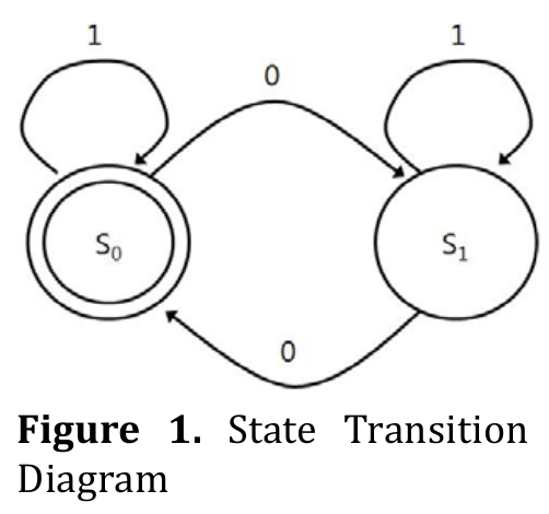
FSM can be described as a state transition diagram. For example, figure 1 depicts state transition diagram where Q= {s0, s1} and Σ = {0, 1}.
For complex problems, the difficulty in representing the system as FSM is how to deal with the state explosion problem. A system with nvariables that can have Z values can have Zn possible states.
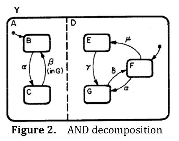
StateChart[1] extends a FSM to have concurrent FSMs which is referred to as AND decomposition or parallel decomposition. As you can see in the figure 2, a system Y can be represented as orthogonal product of subsystem A and D. The transitions in each subsystem can occur simultaneously. This reduces number of states and edges in the FSM solving state explosion problem.
FSM is further distinguished by Deterministic Finite Automata (DFA) and Nondeterministic Finite Automata (NFA). In DFA, for each pair of state and input symbol there is only one transition to a next state whereas, in NFA, there may be several possible next states. Often NFA refers to NFA‐epsilon which allows a transition to a next state without consuming any input symbol. That is, the transition function of NFA is usually defined as T: Q x (ΣU{ε}) → P(Q) where P means power set.Theoretically, DFA and NFA are equivalent as there is an algorithm to transform NFA into DFA [2].
Forces
-
Number of states vs. interaction overhead: FSM can get complicated in terms of the number of states and transitions and hence difficult to understand in general and may cause state explosion problem. If we decompose the FSMs into smaller sub‐FSMs, it makes easier to understand the FSM and reduces the number of states but it incurs the interaction overhead between multiple sub‐FSMs.
-
Memory space vs. traverse time: DFA has less computational complexity than NFA since there is only one unique path for a given string of symbols. NFA requires multiple path tracking for a given string of symbols. On the other hand, DFA will require possibly exponentially larger memory compared to NFA.
Solution
-
Define the states of the system. A state can be a mode of your system or a just single variable depending on the level of abstraction you are describing your system with. If it requires too many states, consider to represent it as concurrent FSMs (AND decomposition).
-
Define the input and output symbol of the system. FSM that generates output symbol string is called Finite State Transducer (FST) and has 6‐tuple, (Q, Σ, T, Γ, m, q0,) consisting of a finite set of states Q,a finite set of input symbols Σ, a transition function T: Q x Σ → Q, a finite set of output symbols Γ, an output function m, and an initial state q0 ∈ Q.The output function can a function of a state and input symbols (Mealy machine), or a function of a state only (Moore Machine). If your system triggers event signals or emit some symbols, it would be natural to describe it as a Mealy machine and if it activates a set of actions or functions than it would be natural to describe it as Moore Machine.
-
Define the transition of the system.You can draw state transition diagram or state transition graph to identify and define the relation between states. If there are too many transitions between states, consider to represent it as hierarchical FSM (OR decomposition) [1].
-
Consider implementation choice of your FSM. You can implement your FSM with an explicit state transition table that contains, for every possible combination, the next state and output symbols or output functions. If the number of states is large and the state transition table is sparse, you can implement it as a graph (i.e., state transition graph).
-
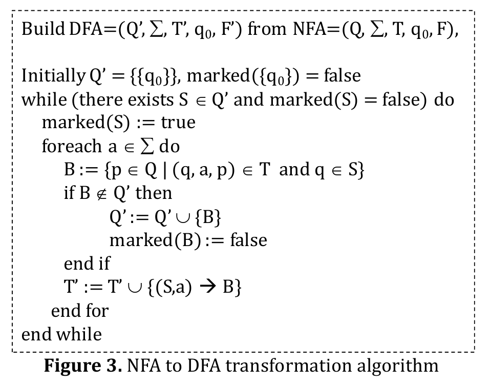
Optimize your FSM. There is an algorithm to transform NFA into DFA and subsequently the number of states in DFA can be minimized to reduce memory space. The pseudo code for NFA to DFA transformation is illustrated in figure 3.

-
Parallelization strategies
(1) NFA has multiple paths to maintain to recognize input string as there can be multiple transitions for a given input symbol in NFA. Each unit of execution (UE) can execute each path in NFA in parallel.
(2) Concurrent FSM has multiple sub‐FSMs and each UE can execute a sub‐FSM in parallel.
(3) Suppose that we have already seen the sequence of input symbols. We can divide the sequence into multiple sub‐sequences of input symbols and execute FSM in parallel with each sub‐sequence. However, we need to know the initial state of each sub‐ sequence. One can resolve this by speculation and re‐execute FSM only if the speculation fails.
Invariant
Precondition: State=q0
Postcondition: For FSMs, if the input string is accepted, then it ends at states in F. For FSTs, a stream of valid output symbols has been emitted.
Example
-
Printing the first word of each line[4]
Consider we need a program in C that reads a text from standard input stream, line by line, and prints the first word of each line. We need first to read and skip the leading spaces, if any, then read characters of the first word and print them until the word ends, and then read and skip all the remaining characters until the end‐of‐line character is encountered. Upon the end of line character (regardless of the stage) we restart the algorithm from the beginning, and in case the end of file condition (regardless of the stage) we terminate the program.
(1)(3) Define the states, inputs and the transitions: We define the system with three states denoted by ‘before’, ‘inside’ and ‘after’. The input symbol is ASCI character set including space and new line character and we denote space by S, new line character by N and the other character by A. Then, we can draw a state transition diagram shown in figure 4.

(4)Consider implementation choice of your FSM: As the number of states and transitions is small in this example, one would implement the FSM with switch statement like shown below. However, if the number of states and transitions are large,
#include <stdio.h>
enum states { before, inside, after };
void step(enum states *state, int c)
{
  if(c == '\n') {
   putchar('\n');
   *state = before;
  } else
  switch(*state) {
    case before:
      if(c != ' ') {
        putchar(c);
        *state = inside;
      }
      break;
      case inside:
        if(c == ' ') {
          *state = after;
        } else {
          putchar(c);
        }
        break;
        case after:
          break;
  }
}
int main()
{
  int c;
  enum states state = before;
  while((c = getchar()) != EOF) {
    step(&state, c);
  }
  return 0;
}
it would be better to implement with state transition table as shown below. In the program below there’s an array named the_table, which defines the table. The rows of the table stand for three states, while columns reflect the input characters (first for spaces, second for the end of line character, and the last is for all the other characters). If the number of states is much larger, a graph where nodes present the states is preferred.
#include <stdio.h>
enum states { before = 0, inside = 1, after = 2 }; struct branch {
  enum states new_state: 2;
  int should_putchar: 1;
};

struct branch the_table[3][3] = {
  /* ' ' '\n' others */
  /* before */ { {before,0}, {before,1}, {inside,1} },
  /* inside */ { {after, 0}, {before,1}, {inside,1} },
  /* after */ { {after, 0}, {before,1}, {after, 0} }
};

void step(enum states *state, int c)
{
  int idx2 = (c == ' ') ? 0 : (c == '\n') ? 1 : 2;
  struct branch *b = & the_table[*state][idx2];
  *state = b‐>new_state;
   if(b‐>should_putchar) putchar(c);
}

int main()
{
int c;
enum states state = before;
while((c = getchar()) != EOF)
  step(&state, c);
  return 0;
}
2. HTMLLexer[5]
Consider we are lexing HTML documents. We need to identify each lexeme from input string in the documents based on the HTML tag specifications. Suppose the specifications are given as:
Content ::= [^<]+ (one or more characters that are not ‘<’)
ETag ::= </[^>]*> (‘<’ ‘/’ followed by zero or more characters that are not ‘>’ ending with ‘>’)
STag ::= <[^>]*> (‘<’ followed by zero or more characters that are not ‘>’ ending with ‘>’)
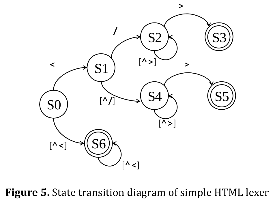
(1)(3) Define the states, inputs and the transitions:We define the system with seven states denoted and define the transition based on the specification. Then, we can draw a state transition diagram shown in figure 5. The convention is that unspecified transitions from accepting states behave as transitions from initial state. The state S5 recognizes STag and S3 does ETag and S6 does Content.
(6) Parallelization strategies
As well as other FSM problem, lexing is inherently sequential processing in that the current state is based on the previous state. However, we observe that HTML lexers converge to a stable, recurring state after a small number kof characters. In figure 5, most of characters stay at state S6. This allows us to speculate the execution of the HTML lexer. We spilt input into blocks with k‐character overlap and scan blocks in parallel, each starting from S6. If speculation fails (i.e. does not converge in k‐overlap), the block is rescanned.
Known Uses
-
Parser/Lexer
GNU Flex, egrep, XML transformation (xalancbmk benchmark)
-
Weighted Finite State Transducer (WFST)[3]
Text and speech processing, computational biology, image processing (OCR)
-
Fuzzy State Machine (FuSM)
-
Compression
bzip2, Huffman decode (VLD)
-
Control applications
Automotive applications: Angle to time, cache “buster”, CAN Remote Data, PWM, Road Speed
Related Patterns
- Graph algorithms: Efficient traversal on State transition graph relates to graph algorithm pattern.
- Event‐based, implicit invocation: The output in FSMs for control applications are usually events that implicitly invokes other FSMs or module.
- Discrete event
References
[1] David Harel, “Statecharts: A visual formalism for complex systems. Science of Computer Programming”, 8(3):231–274, June 198
[2] John Hopcroft and Jeffrey Ullman, “Introduction to Automata Theory, Languages, and Computation”, Addison‐Wesley Publishing Company, Reading Mass, 1979
[3] Mehryar Mohri, Fernando C. N. Pereira, and Michael Riley, “Weighted Finite‐State Transducers in Speech Recognition”, Computer Speech and Language, 16(1):69‐88, 2002.
[4]http://en.wikipedia.org/wiki/Automata-Based_Programming
[5] Christopher Grant Jones, Rose Liu, Leo Meyerovich, Krste Asanović, and Rastislav Bodik, “Parallelizing the Web Browser”, First USENIX workshop on Hot topics on Parallelism
Authors
- Original Author: N.R. Satish
- Revised: Youngmin Yi